Jaw Style Coupling Selection Method
The variety system for identifying the proper jaw coupling dimension and elastomer needs using the charts shown to the following pages. You will discover three components to be picked, two hubs and a single elastomer. Once the shaft dimension with the driver and driven in the application are on the very same diameter, the hubs selected is going to be the identical. When shaft diameters vary, hubs chosen will vary accordingly.
Data vital just before a coupling can be selected:
HP (or KW) and RPM or Torque of driver
Shaft sizes of driver and driven products and corresponding keyways
Application description
Environmental problems (i.e. excessive temperature, corrosive ailments, area limitations)
Ways In Selecting A Jaw Coupling
Phase one: Decide the Nominal Torque of one’s application through the use of the following formula:
Nominal Torque = in-lb = (HP x 63025)/RPM
Nm = (KW x 9550)/RPM
Stage two: Utilizing the Application Support Aspects Chart one decide on the support issue which ideal corresponds for your application.
Phase 3: Determine the Design Torque of your 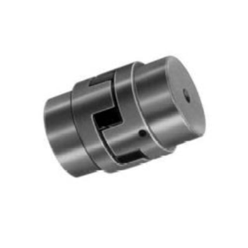 application by multiplying the Nominal Torque calculated in Step 1 through the Application Support Factor determined in Stage two.
Design and style Torque = Nominal Torque x Application Service Aspect
Phase 4: Making use of the Spider Functionality Data Chart 2, select the elastomer materials which most effective corresponds for your application.
Step five: Employing the Jaw Nominal Rated Torque Chart three , locate the ideal elastomer materials column for that elastomer picked in Phase four.
Scan down this column towards the to start with entry in which the Torque Value in the ideal column is greater than or equal to the Style and design Torque calculated in Step 3.
Once this value is found, refer for the corresponding coupling size inside the initially column of your Jaw Nominal Rated Torque Chart three .
Refer to your highest RPM worth for this elastomer torque capability to make sure that the application prerequisites are met. Should the requirement is not pleased at this point, yet another form of coupling could possibly be expected for that application. Please consult Lovejoy engineering for help.
Stage six: Review the application driver/driven shaft sizes to your optimum bore dimension available within the coupling picked. If coupling bore dimension just isn’t large sufficient for your shaft diameter, select the following largest coupling that should accommodate the driver/driven shaft diameters.
Step seven: Applying the UPC variety selection table , discover the suitable Bore and Keyway sizes required and find the variety.